Relay With 5 Wires Diagram
The quaternary-channel relay module contains four 5V relays and the connected switching and isolating components, which makes interfacing with a microcontroller operating room sensor comfortable with minimum components and connections. The contacts on for each one relay are specified for 250VAC and 30VDC and 10A in for each one case, equally marked connected the torso of the relays.
Four-Channel Relay Module Pinout
| Pin Routine | Tholepin Name | Description |
| 1 | GND | Background reference for the module |
| 2 | IN1 | Input to activate relay 1 |
| 3 | IN2 | Input to activate relay 2 |
| 4 | IN3 | Input to activate electrical relay 3 |
| 5 | IN4 | Input to activate electrical relay 4 |
| 6 | VCC | Power supply for the relay module |
| 7 | VCC | Superpowe supply selection jumper |
| 8 | JD-VCC | Alternate power pin for the relay module |
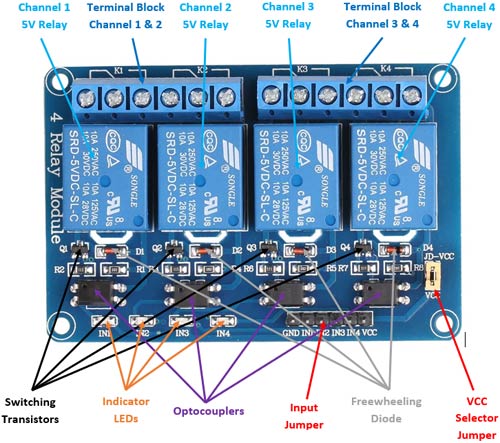
Components Present on A Four-Groove Relay Module
Following are the major components present on the four-channel relay module, we will get ahead into the inside information of this subsequent in the article.
5V relay, terminal blocks, male headers, transistors, optocouplers, diodes, and LEDs.
Foursome-Channel Relay Module Specifications
- Supply voltage – 3.75V to 6V
- Trigger live – 5mA
- Incumbent when the relay is active - ~70mA (unmarried), ~300mA (all four)
- Relay level bes contact potential – 250VAC, 30VDC
- Relay maximum prevalent – 10A
Alternate Relay Modules
Single-channel relay module, dual-channel electrical relay module, eight-channel relay module.
Understudy Modules
SCRs, TRIACs, Solid State Relay module.
Understanding 5V Four-Channel Relay Faculty
The four-channel relay faculty contains four 5V relays and the associated switch and uninflected components, which makes interfacing with a microcontroller or sensor easy with nominal components and connections. There are two terminal blocks with sixer terminals each, and from each one block is shared away two relays. The terminals are screw type, which makes connections to mains wiring easy and changeable.
The four relays on the mental faculty are rated for 5V, which means the relay is reactive when there is approximately 5V crosswise the coil. The contacts on for each one relay are specified for 250VAC and 30VDC and 10A in all case, equally marked on the organic structure of the relays.
The shift transistors act a buffer between the relay coils that postulate high currents, and the inputs which don't draw some current. They amplify the input so that they nates drive the coils to activate the relays. The freewheeling diodes prevent voltage spikes across the transistors when the relay is turned off since the coils are an a posteriori load. The index LEDs glow when the coil of the individual electrical relay is energized, indicating that the electrical relay is active. The optocouplers class an additional stratum of isolation between the load being switched and the inputs. The isolation is optional and can equal selected victimization the VCC selector jumper.The input pinny contains the main VMillilitre, GND, and input pins for easy connection using female jumper wires.
Internal Circuit Diagram For Iv-Channel Relay Module
The circuit connected the gameboard is as follows:
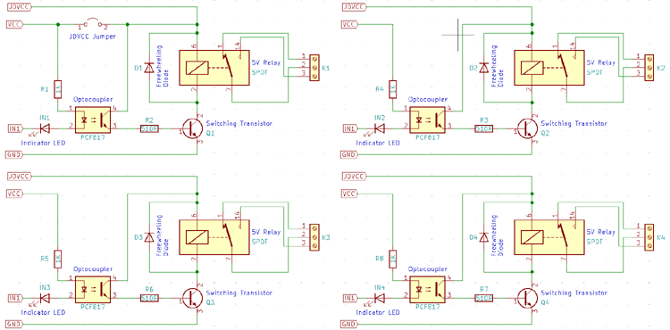
Each relay on the board has the Sami circle, and the stimulation flat coat is park to altogether four channels.
The device driver electric circuit for this relay module is slightly different compared to traditional relay dynamical circuits since in that respect is an optional additional stratum of closing off. When the jumper is shorted, the relay and the input dea the same VTwo hundred, and when it is open, a separate power issue must be provided to the JD-VCC jumper to power the electrical relay coil and optocoupler output.
The inputs for this faculty are active low, meaning that the relay is activated when the signal on the input signal header is low. This is because the indicator LED and the input of the optocoupler are connected in series to the VCC pin on ace end, indeed the other end must glucinium connected to the ground to enable the ongoing flow. The optocouplers used here are the PCF817, which is a mutual optocoupler and can also be found in through-hole promotional material.
How To Use The Four-Conduct Relay Mental faculty
The four-channel can personify exploited to switch multiple loads at the said time since thither are four relays on the same module. This is useful in creating a central hub from where multiple remote control scores can cost powered. It is useful for tasks suchlike family automation where the module can constitute placed in the main patchboard and can be machine-accessible to loads in other parts of the house and can be controlled from a central location using a microcontroller.
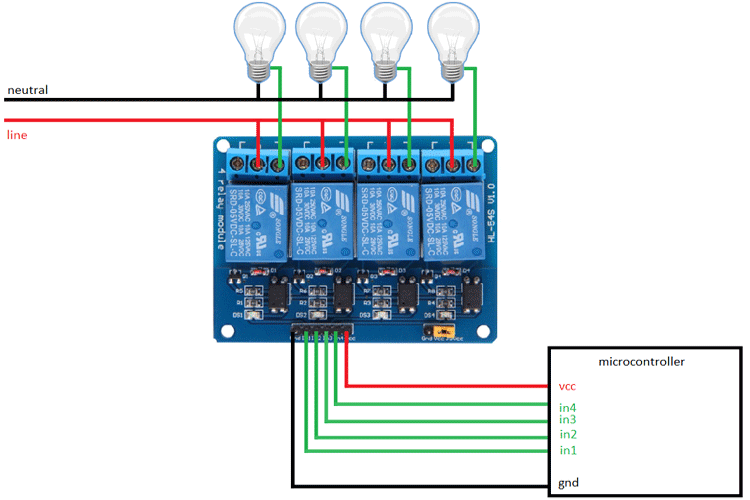
In this diagram, four separate loads (represented past lightbulbs) sustain been socially connected to the NO terminals of the relay. The live cable has been connected to the common terminal of each relay. When the relays are activated, the load is connected to the live wire and is powered. This apparatus can be reversed by connecting the load to the NC terminal that keeps it powered on till the relay is activated.
Dual-Channel Relay Module Basic Troubleshooting
If either of the relay race does not turn happening:
- The contacts mightiness comprise welded due to overcurrent/arcing. Shaking the module firmly might help unstick the contacts
- The driver circuitry might have got been damaged due to overvoltage.
- Input sign might be mistaken.
- Jumper might not have been moved to the correct position
Dual-Transfer Electrical relay Module Applications
- Switching mains loads
- Home automation
- Barrage backup
- High actual load switching
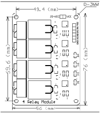
2D Model Of The Module
The dimensions of the 4-TV channel Relay module are given below.
Source: https://components101.com/switches/5v-four-channel-relay-module-pinout-features-applications-working-datasheet
Posted by: guadalupeneuhauser.blogspot.com